August 31, 2025
3D Modeling with Paper
Over the past several years, I've enjoyed the hobby of paper modeling (or papercraft), the art of creating 3D models from cut and glued parts from paper sheets. This hobby is a superset of origami, in that it allows for cutting and gluing, as well as for multiple sheets of paper for a single model. The alleviation of these constraints means that papercraft allows for more complex models that are easier to assemble.
Over many years, I've built models designed by others as well as designed my own. In this post, I want to share everything I've learned along the way, covering the entire process from design to assembly.
I love this hobby for three reasons:
- It is extremely accessible. There is no fancy hardware or software involved. As we'll see, the core tools are paper, scissors, and glue; everything else is an addon to make the experience better. All software tools can be free. Accidentally messed up during assembly and need a replacement part? Just print out another page. The entire creation of a model can be done in the ballpark of a few cents.
- It is equally technical and creative. As we'll see, many of the problems faced in papercraft require an engineering-like approach and a willingness to experiment and iterate on designs. While it may appear outwardly like a craft project, the end-to-end process involves constraints and optimizing within them.
- There's no limits on what you can make. What you decide to build is limited by your patience and imagination. Theoretically, nearly any object can be represented as a paper model.
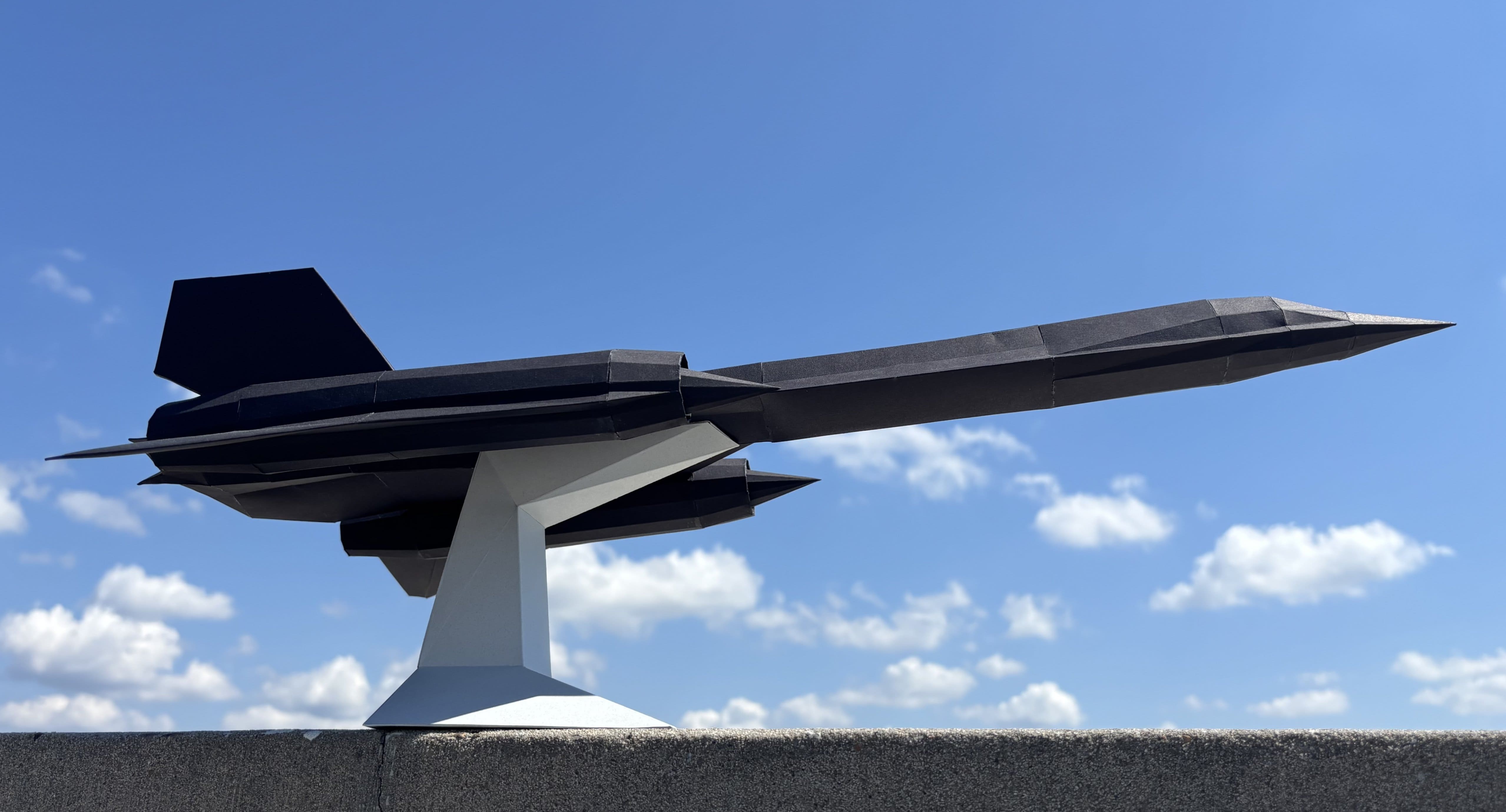
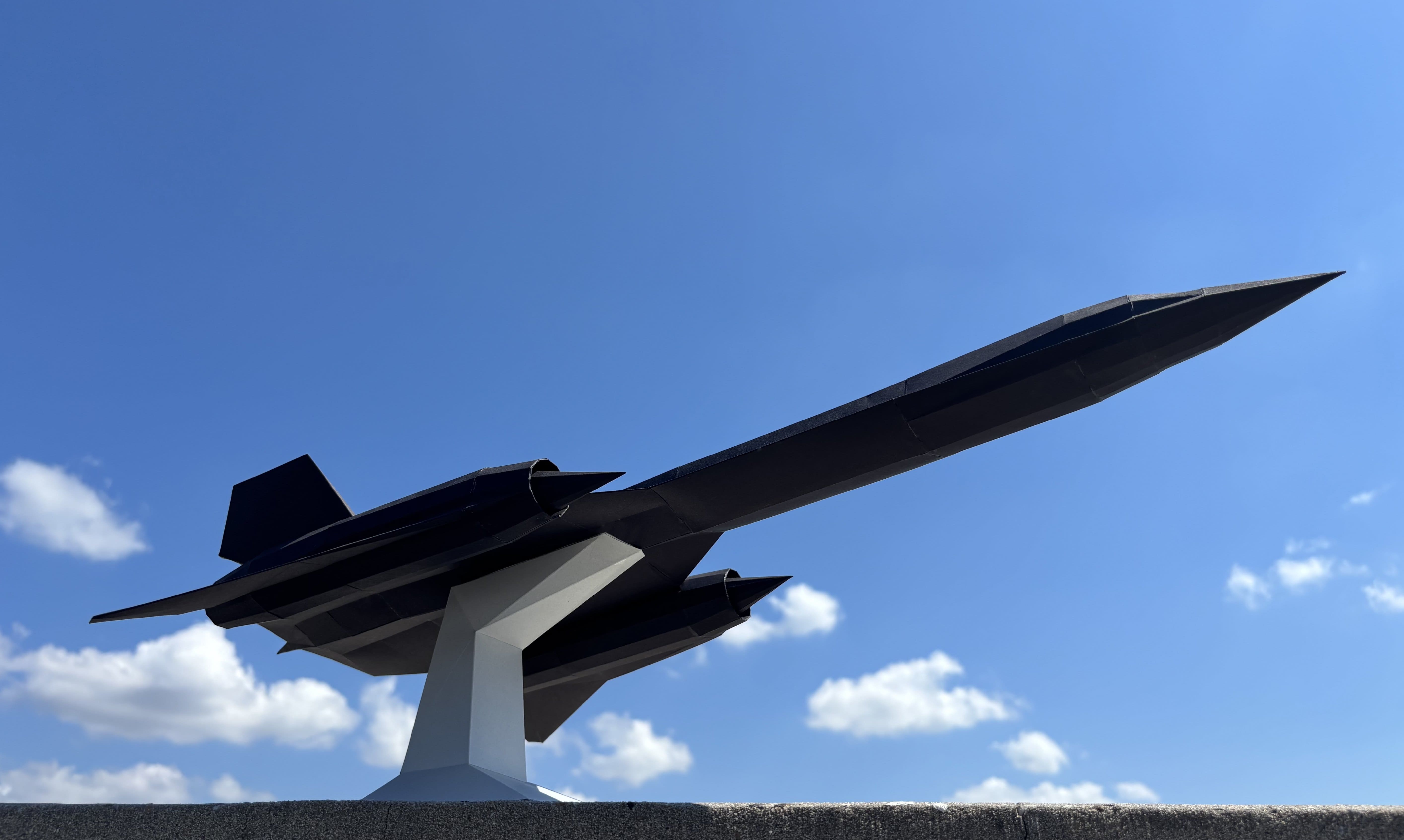
Let's dive in. My most recent model is a papercraft plane inspired by the SR-71 Blackbird, a reconnaissance plane that to this day holds many records for being one of the fastest aircrafts ever. It's now one of most iconic planes ever designed and an engineering masterpiece. The program was ultimately retired in 1999.

We're going to walk through the full model design and assembly process, while referencing specific examples I encountered during creating this SR-71.
Constraints#
Let's set some constraints for how we're allowed to model our creation. These are self-imposed limitations that fit my preferred-style for model design:
- All parts in the assembled model must be made of paper.
- Each part must be a single, solid color. The parts must not use any printed textures or designs.
- The model must be represented as a simple polyhedron. There may be no curvatures, holes, two-dimensional surfaces, or surface-to-surface contact. If the figure we're trying to capture has any of these features, we must find a way to approximate it using only flat faces. The object must be manifold (an edge is only shared by 2 faces).
Why constraints?#
It may feel weird to impose constraints on an art. However, I find that these constraints encourage a better designed model that can be assembled easily and predictably, including by others.
Using features like curvatures, printing with textures, etc. are shortcuts. For example, printing textures helps fill in details that aren't captured inherently by the model; curvatures and 2d surfaces are flimsy and introduce variances in how a model can be assembled. Simply polyhedral designs with single color parts ensure that the 3D form itself captures the object being depicted, and can be assembled in a structurally sound, predictable way.
Goals#
In addition to constraints, we also have some goals that we're optimizing for. These goals will be considered in each step of our design process.
- Ease of assembly: By far the most important goal, our model should be easy to put together. Given the nature of paper and glue, a model that is difficult to assemble will almost certainly look bad. A model can have a well-designed topology, but still be difficult to assemble based on the parts design we put together.
- Aesthetic appeal: This is an art, after all. The model we design should be aesthetically pleasing and resemble the object of interest.
- Minimal consumption of resources: We should aim to minimize waste and use our materials efficiently.
As in engineering, we have to consider trade-offs between these goals, and optimize for these goals within our constraints.
Steps#
The process of designing a paper model is iterative. Each iteration consists of the following steps:
- Mesh modeling - using software to create a 3D polyhedron mesh of our desired form
- Mesh unfolding - unfolding the mesh into a 2D layout of parts
- Assembly - putting the parts together to create the final model
The remainder of this article will be walking through each step in detail. The discussion of each step will be centered around the goals and constraints declared from above.
Mesh Modeling#
Related goals: Ease of assembly, aesthetic appeal
In this phase, we design the mesh for our model. We aim to capture the essence of an object in a way that can feasibly be built with paper. Depending on how you approach this, this can easily be the most complicated step.
What do I mean by "feasibly built with paper"? Our mesh is a collection of polygons that represent a 3D object. The closeness of that representation is largely determined by how many polygons we use. We could use many really small polygons to closely match the subtle curves of our plane, but this would be hard to assemble in reality. Alternatively, we could simplifiy our representation down to a triangular pyramid. This would be trivially easy to assemble, but it wouldn't look a lot like our plane.
We can now see that our goals of ease of assembly and aesthetic appeal are at odds. Imagine that we have a continuum, where on the left we have a triangular pyramid (the simplest possible polyhedron) and on the right we have a mesh of the SR-71 with an arbitrarily high number (millions) of polygons.
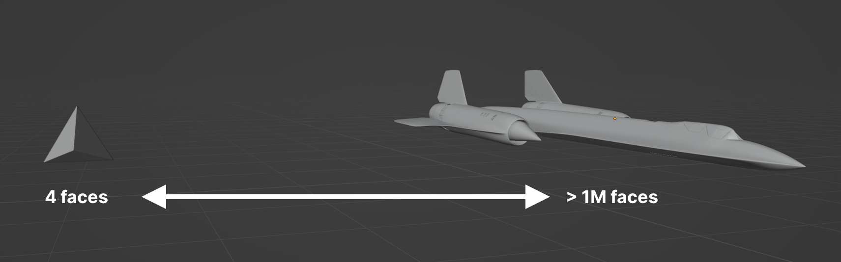
Generally, an "easy" to assemble model will have somewhere around a few hundred polygons. Thus, our ideal model exists somewhere on the far left of this spectrum.
The challenge here is what I call "allocation of resolution" - we have a finite number of polygons to distribute across the features of our object. Certain features will naturally require more polygons to be accurately captured than others. For example, curved features require more polygons than flat features - in this model, the cylindrical engines will require more detail, than say, the flat wings.
In addition to the number of polygons and their concentrations, the arrangement of the polygons themselves matters - this is the topology of the mesh. Most discourse on 3D mesh topology is related to shading and animation. For our purposes, we're considered with ease of assembly. Certain topologies are easier to assemble and more structurally sound. Generally, here's some positive topological qualities for papercraft:
- Symmetries: a good mesh design is symetrical when possible. Symmetrical shapes are intuitive and easier to reason about when assembling.
- No narrow shapes: really narrow shapes are hard to cut out, hard to fold, and hard to glue. Avoid them at all costs.
- Use quads: quad faces have an aesthetic appeal to them.
If all of this is sounding hard, we've got some options, in increasing order of difficulty:
Easy: Use an existing mesh#
The easiest way past this step is to find an existing mesh. There's a whole genre of 3D modeling called "low-poly" that you can find with a quick search on Thingiverse or Printables. These are usually designed for video games or 3D printing, but can be taken up for papercraft.
Medium: Converting an existing mesh#
Sometimes, you can find a high-resolution mesh of your desired object, but not a low-poly one. In this case, there are tools available to reduce the polygon count while preserving the overall shape. This is called "mesh simplification" or "mesh decimation."
This Instructable goes over the process of doing this with Meshlab, but there's many other software alternatives out there.
The pitfall of this approach is that automatic mesh decimation typically results in some nasty topologies, and there's not a lot you can do to control the output. To get around this, we could add an additional refinement step where we take the raw decimated mesh output and "clean it up" using a mesh editor software.
As an example, let's try this with a SR-71 mesh on Thingiverse. The original mesh has more than 1.2 million faces, and we're going to try decimating down to ~1,000. Here's what we get from Meshlab:
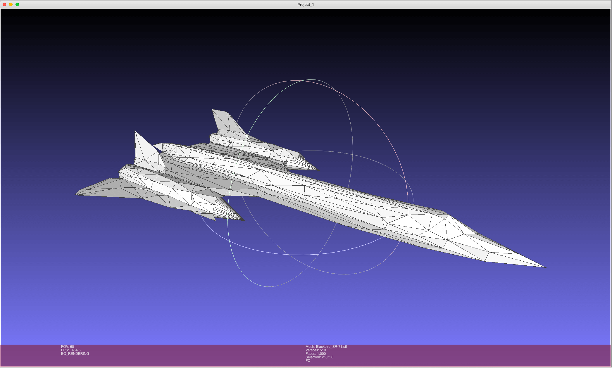
In this case, the output is not usable - it's wildly asymetric and is full of self-intersections. Refining this topology would take just as long (if not longer) as creating a model from scratch.
Hard: Creating your own mesh#
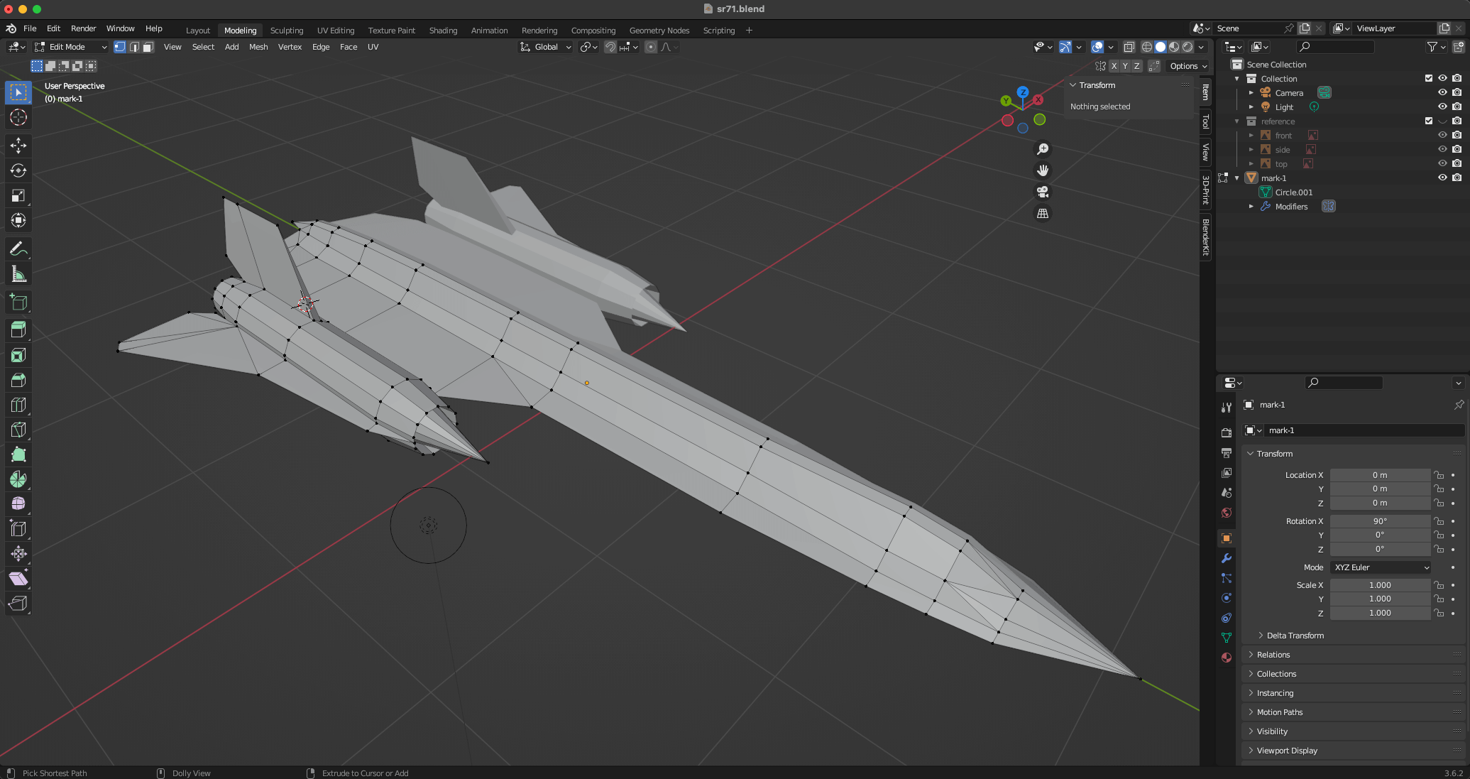
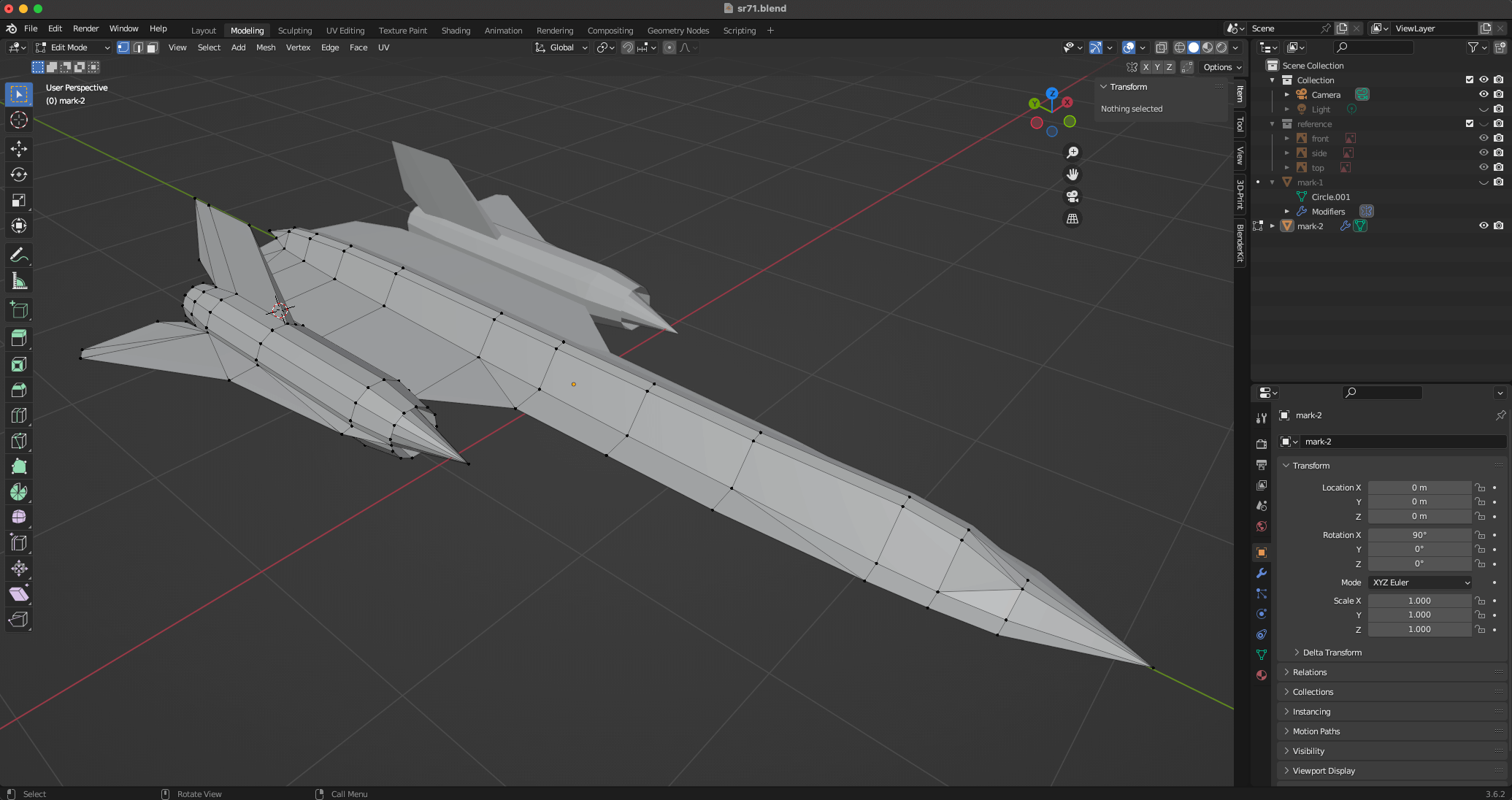
The most difficult option is to create your own mesh from scratch. This option gives you full control over the design, and is what I chose for the SR-71 model.
My software of choice for this is Blender. Blender has a steep learning curve, but the type of mesh design we're doing for this project doesn't begin to scratch the surface of its full capabilities. I highly recommend this low-poly tutorial if you've never used Blender before and need somewhere to start. Two things I found very handy were the mirror modifier to enforce symmetry, and the 3D Print Toolbox to auto-cleanup the mesh and check for manifoldness.
This process is very tedious. My advice here is: simplify your mesh to the point where you feel uncomfortable. Recall that we're largely optimizing for ease of assembly. When modeling, it's very tempting to capture finer details, but fine details have costs (small parts, hard to glue regions, etc.) that are not worth it during the assembly phase. Scrutinize every feature, and zoom out once in a while. When you zoom out, your omissions won't feel as weird.
After many days, here's the initial mesh I created. It contains 732 triangles. Note the symmetry along the y-axis.
Mesh Unfolding#
Related goals: Ease of assembly, minimal consumption of resources
Once we have a mesh, we have to convert it into a 2D template of parts that can be printed and assembled. This process is called unfolding. Each of the faces of our mesh are grouped into parts, and the arrangement of our parts is a layout, or template.
To do this, we're going to turn to software again. The most popular unfolding tool (and my favorite) is Pepakura Designer. Pepakura is not free (at the time of this writing, it's a one time $70 purchase) and it only runs on Windows. There's also Unfolder for Mac, which is $30. If you can't use either of these, Blender can save the day again with its free Paper Model plugin.
I believe that the unfolding step is one that does not get as much attention as it deserves. There is a noticable difference between a good template and a bad one. A good template has parts that make intuitive sense, with logical groupings and clear flow. The faces themselves are grouped into parts that are easy to cut out and handle. All of this equates to a better building experience, which means a better looking model.
Part of unfolding is also deciding the scale of your model. You can make your model as big or small as you want, but again, ease of assembly should be top of mind when deciding. A model that's too small will end up with parts that are hard to cut out and fold. Bigger models are easier to assemble, but you're limited to the point where the faces of your model must fit on a page.
I ended up making this model 25 inches long. With the original SR-71 being about 107 feet long, this puts our model at around a 1:50 ratio.
Creating many parts#
Let's start off with the creation of parts. In most unfolding software, the software will auto-unfold for you, and from there you can regroup faces into whatever parts you want. Here's Pepakura's auto unfold:
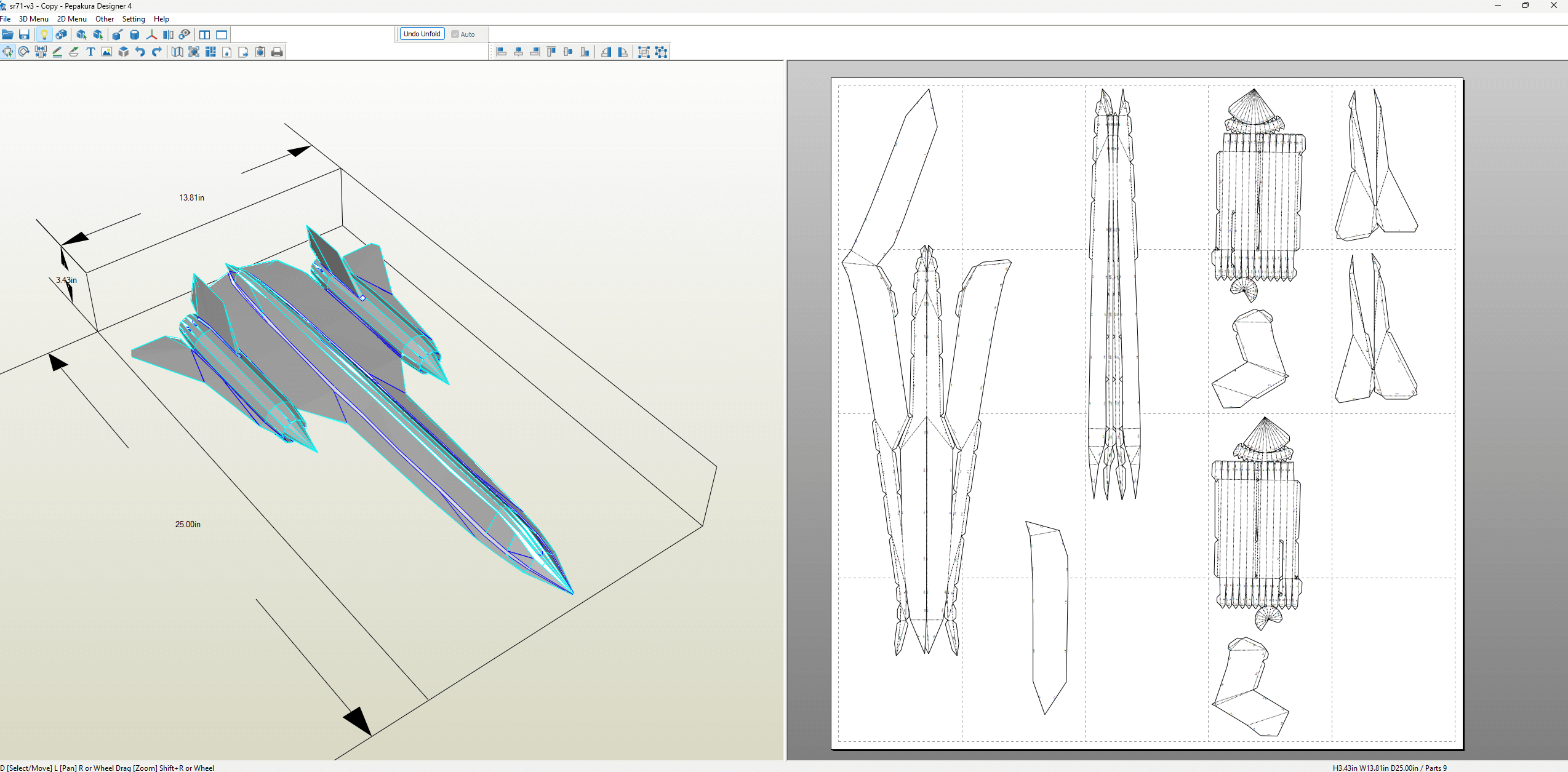
The parts it generated are pretty complicated, so we have some work to do.
If you have a mesh with faces, you can have anywhere from 1 (all the faces in a single part) to total parts (each part is a single face). We want our model to be easy to assemble, and neither of these extremes are easy.
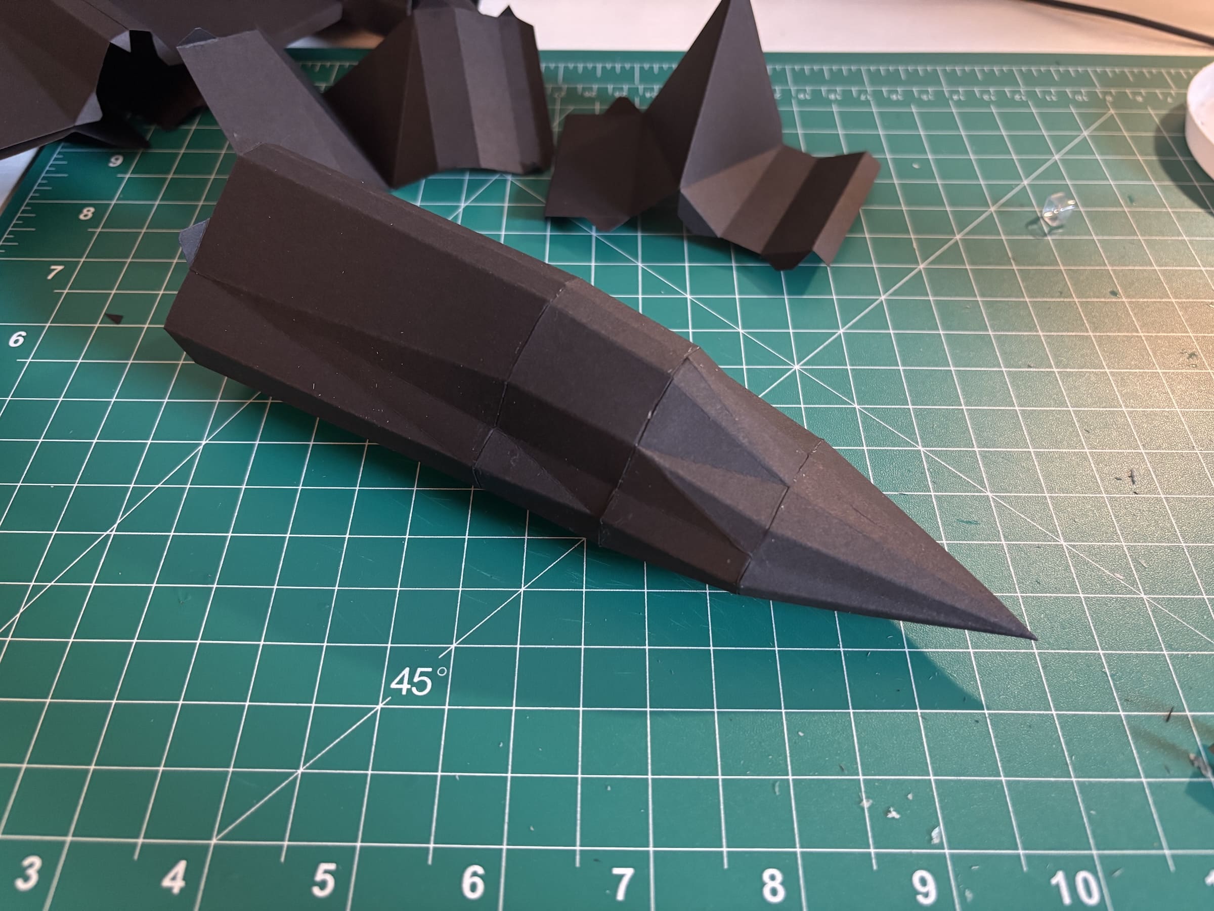
Rather than trying to fix the number of parts and going from there, I recommend creating parts that are logical. Identify features that can be captured in a single part, and go from there. For example, in the SR-71, each engine intake spike makes sense as a single part. So does the nose cone.
If your mesh has an axis of symmetry, then your parts have symmetrical pairings as well. The same feature on either side of the axis should be represented with a mirrored part. In the SR-71, the entire plane is symmetrical on the vertical axis, so all parts across this axis are mirrored. This is good because once someone builds one side, they can more easily reason about the other side.
I ended up dividing this model into 42 parts. These parts were carefully divided in such a way that I felt would make them easier to assemble. If you look at any part in particular, chances are it'll have a symmetric counterpart.
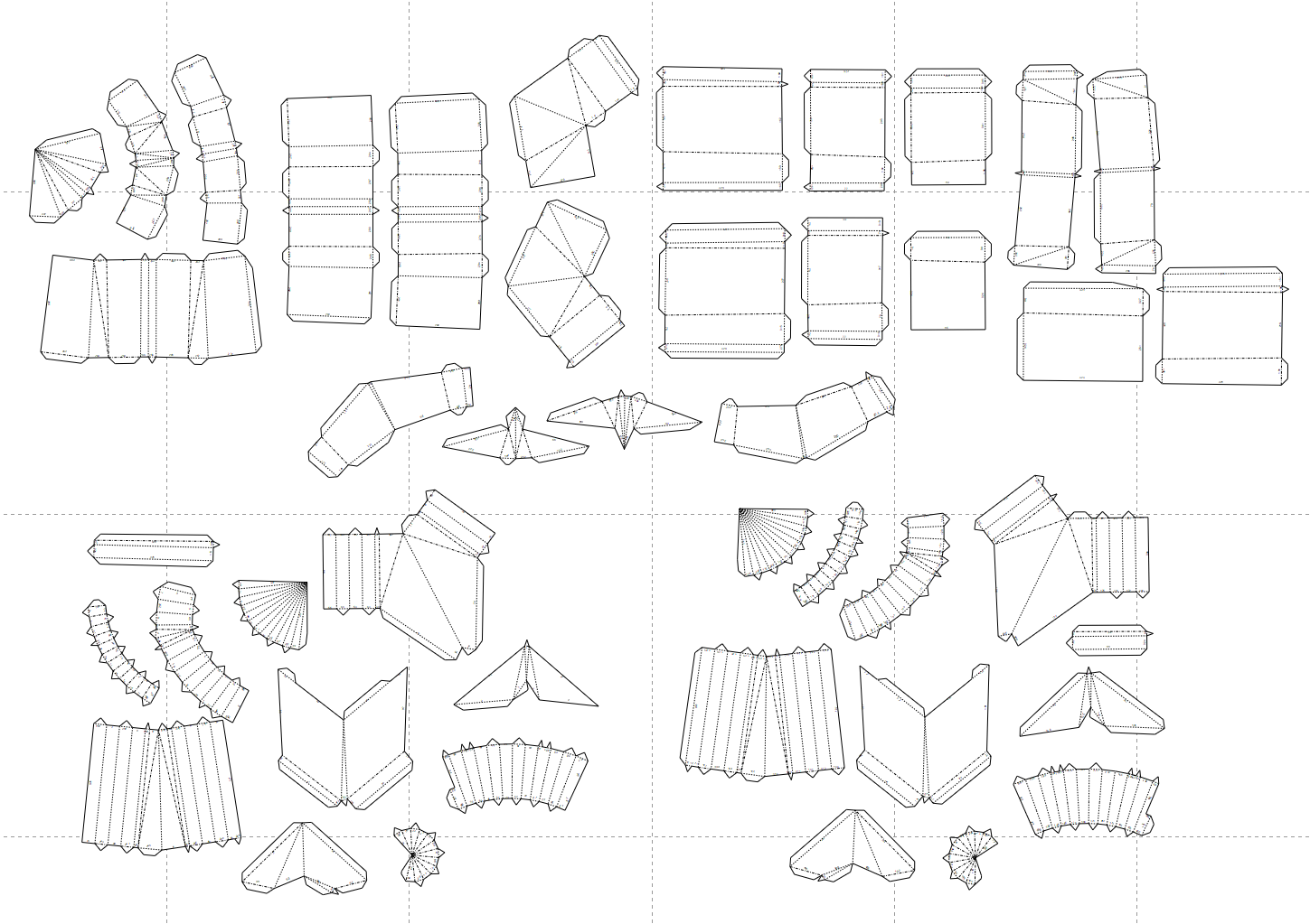
They're arranged pretty haphazardly right now, but we'll clean this up in the next step.
Arranging the parts#
Again, most software will automatically arrange the parts for you as part of unfolding. Here's the 14 page arrangement Pepakura decided for the parts I created:
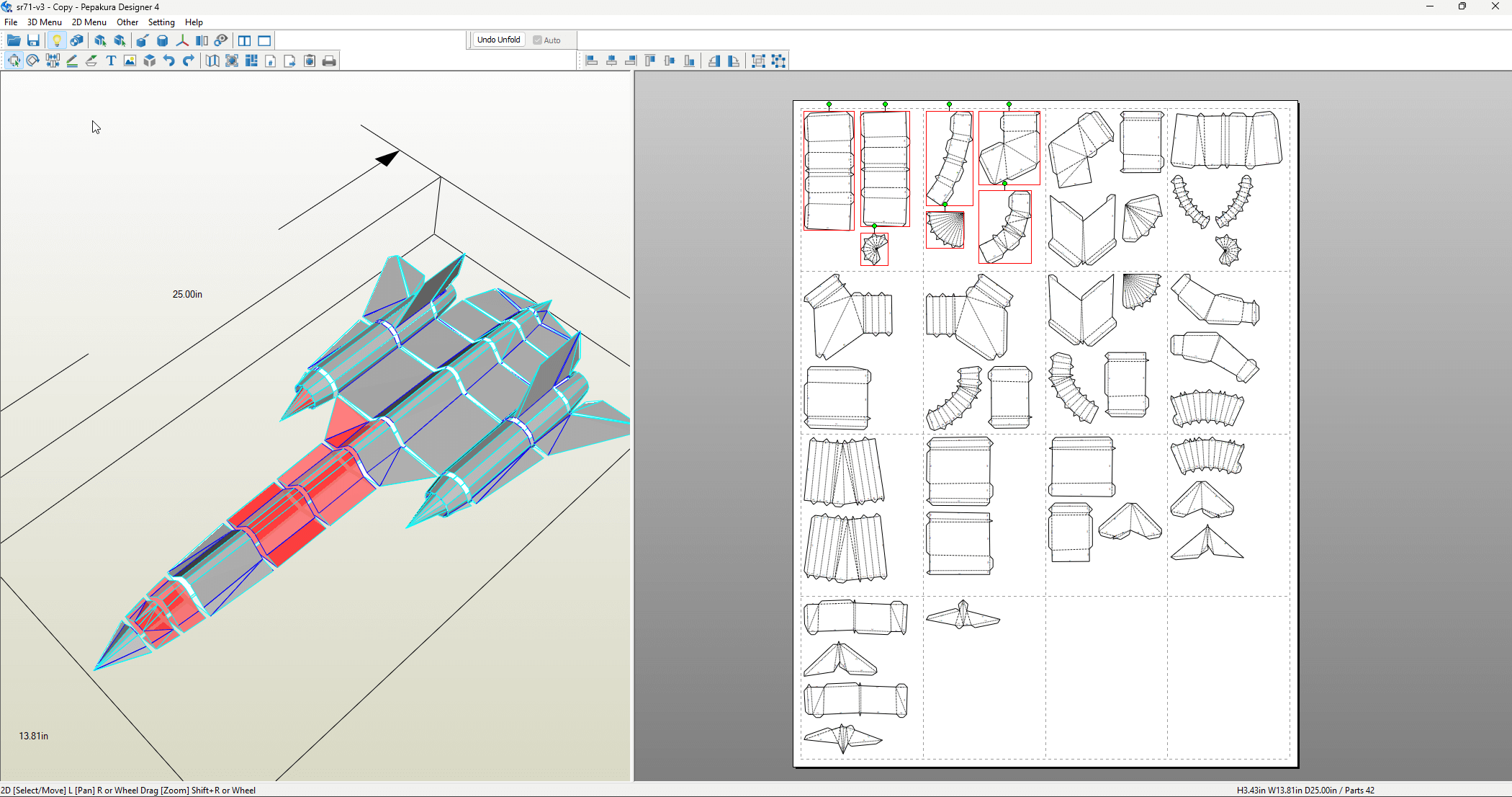
I highlighted all the parts on the first two pages so you can see where the are on the finished model. Notice that they're scattered throughout different sections. That's why I typically don't like auto-arrangement - they're designed to minimize paper usage, but they often result in a less intuitive assembly process. You can't look at any particular page and loosely know where its parts will go.
A good part layout reads like a story. Parts are arranged in a logical order, with related parts grouped together. I like to arrange mine left to right, top to bottom on a page. Here's my layout, with the first two pages highlighted.
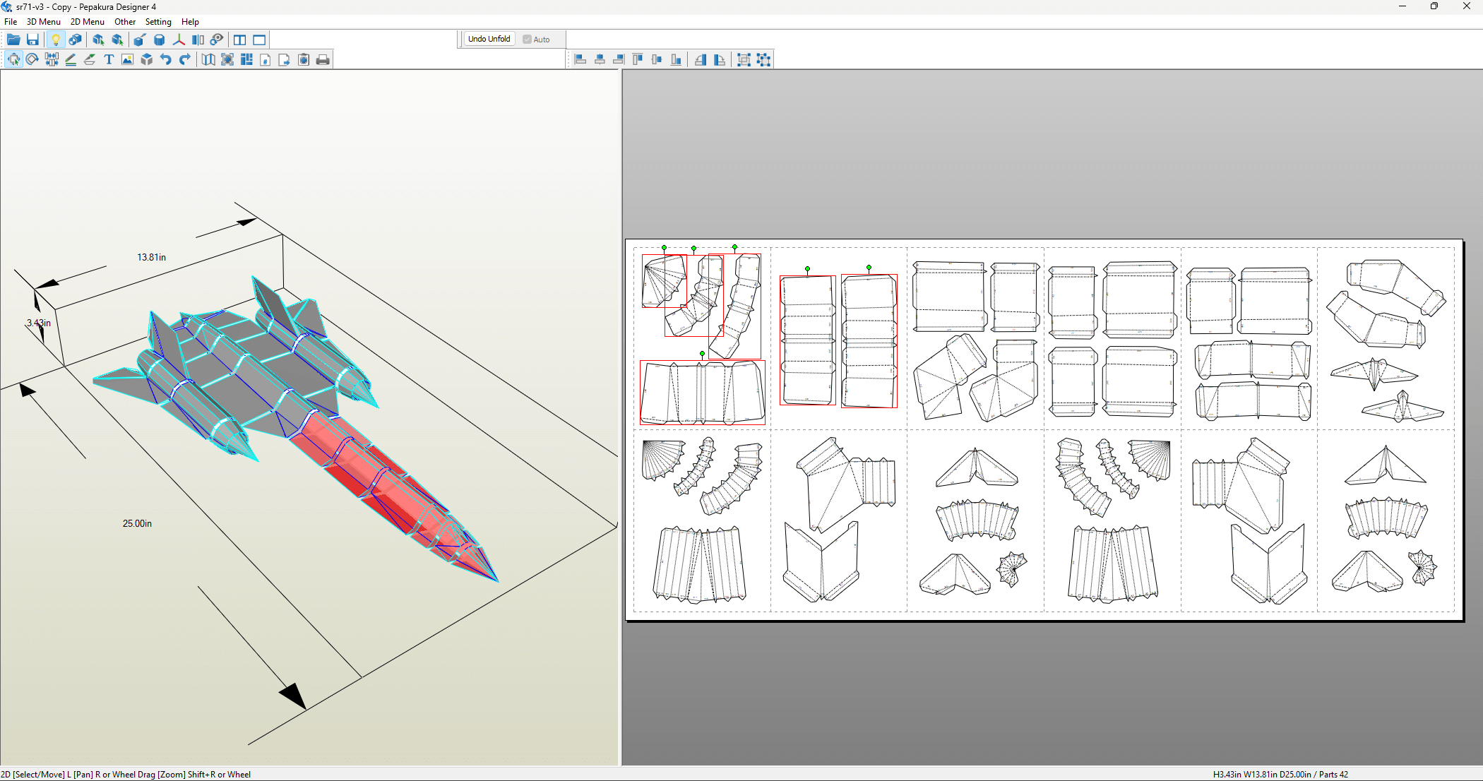
All the parts that are near each other in the layout are also near each other in the final assembly. In this case, I even was able to reduce the page count down to 12 from the starting 14.
Flap structure#
Flaps, or tabs, are the appendages on each part that allow for gluing parts together. Each flap has a singular counterpart edge that it's glued to - this is known as an edge/flap pair. Most software will auto-assign a shared number between an edge and its flap to make identify pairs easy during the assembly process.
For an edge/flap pair, most unfolding software will allow us to swap the flap across parts. Doing this strategically is critical for creating an easy to assemble model, and also has implications for the structural integrity of the final build.
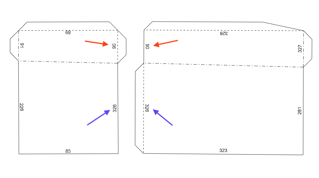
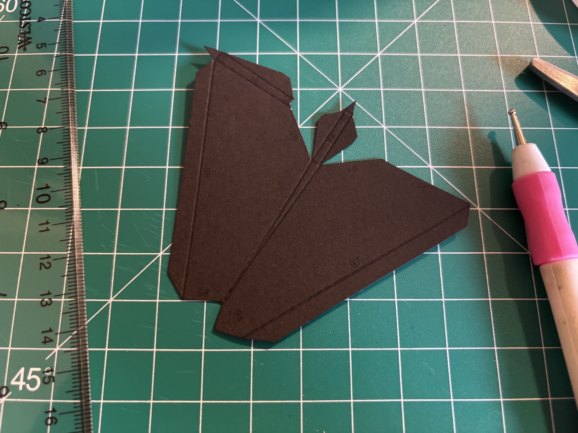
For example, consider the two example parts shown above. These two parts that meet at two shared edges, so these parts have two edge/flap pairs between them. We could arrange the flaps so that one part has both of them:
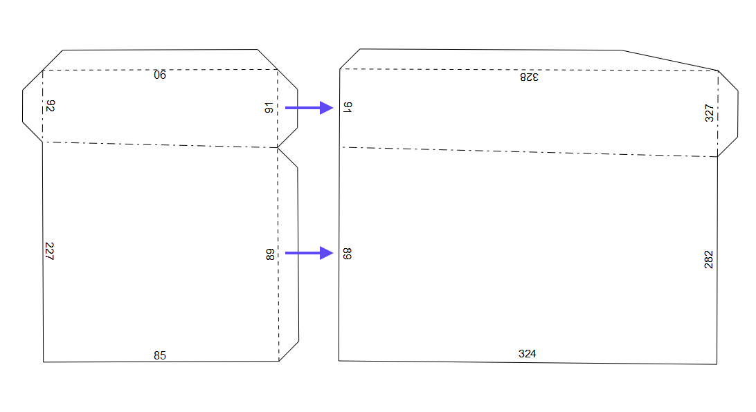
We could also interlace the flaps, so each part has one flap on each side.
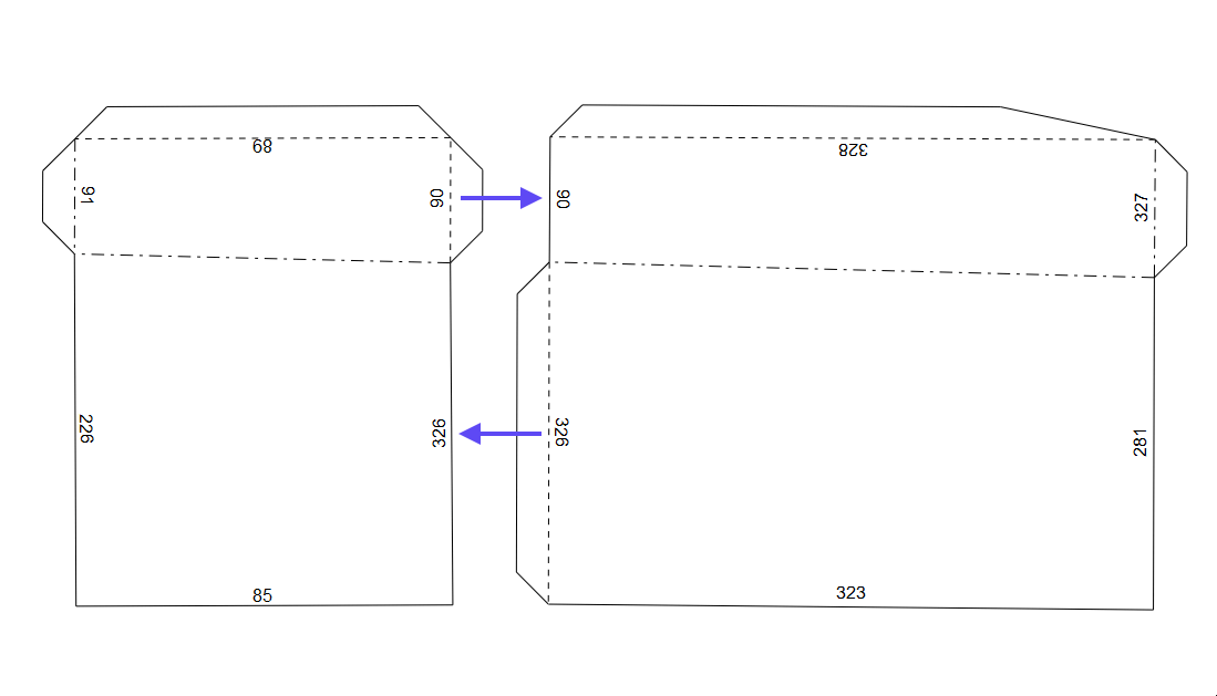
Interlacing flaps between parts can create a more stable structure, since there's only one way for the parts to meet. If two flaps are on the same side, they can over-extend when glued to the edge. That being said, same-side flaps can be easier to work with, especially when reaching the closing stages of a model.
In general, I like to using interlaced flaps wherever possible to create an overall stronger model, and use same-side flaps selectively.
Once we have an arrangement we like, we can export our layout as a PDF.
Assembly#
With our layout PDF ready, we can now print it and move on to assembly. We'll finally get to see our design come to life.
Materials and Tools#
For our materials, we'll need:
- 65lb (176 ) cardstock: This is the ideal paper weight for creating sturdy models, while still being thin/flexible enough to pass through a normal printer and be easy to fold.
- Adhesive. My recommended adhesive is tacky glue: it's strong, dries clear, but is forgiving enough to allow for repositioning during assembly. Specifically, I use Aleene's Original Tacky Glue. I've also had past success with a glue stick.
We'll also need some tools, which I've listed these in order of importance. The ones with asterisks are essential. Everything else is a nice-to-have.
- Printer*: You'll need access to a printer to print the template on the cardstock. Laser jet printers are great because the prints don't smudge.
- Cutting tools*: You'll need a pair of scissors or a craft knife to cut out the parts. Use sharp tools for clean cuts - it makes a difference.
- Ruler*: Cutting/scoring perfectly straight lines is a must. Steel rulers are great for their consistent edge, and they don't catch against your tools. That being said, I used a clear plastic ruler for this model. Being able to see through the ruler helps with alignment.
- Scoring tool*: This will help you prepare a part for folding. You can use a bone folder or scoring wheel. I use an embossing tool I found at a dollar store, but before that, I used a ballpoint pen than ran out of ink. Anything with a precise (but not too sharp) tip will do.
- Toothpicks: I use toothpicks to spread blobs of glue into thin layers and get into tight spaces.
- Assembly surface: A cutting mat or piece of cardboard will protect your work surface and give you a stable surface to cut/score your parts.
- Tweezers: Tweezers are helpful for handling small parts and getting into tight spaces, especially while holding parts together as glue dries.
If you want to get fancy, you can also purchase an automatic cutting machine, like a Cricut or Silhouette. These machines can precisely cut/score your parts from cardstock. Getting the template into their software takes some extra effort, but it results in the best quality parts. I did not use a machine for this project.
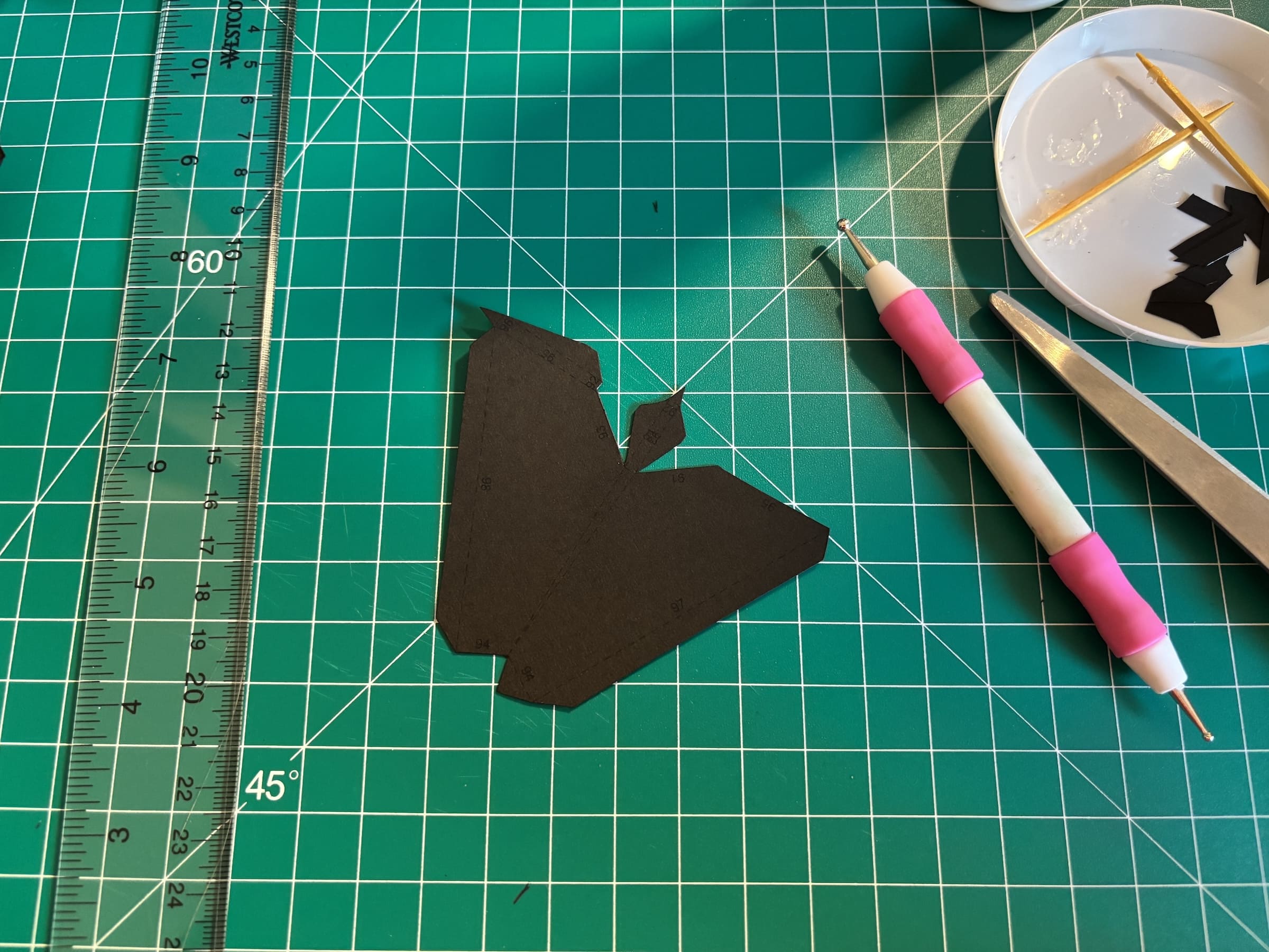
To match the real SR-71, I printed my template on black cardstock. Darker cardstocks are harder to work with because of the low contrast between the ink and the paper itself. If you're new to the hobby, I would recommend starting with a lighter color.
Assembly phases#
The assembly of a model has 4 steps:
- Cutting: Cutting the parts out from the paper with your cutting tool of choice. Scissors are quicker, but the combination of ruler and craft knife results in cleaner cuts.
- Scoring: Running a scoring tool over fold lines to get cleaner folds. This may be tempting to skip, but I cannot emphasize the importance of this step enough. Scoring is especially important when dealing with thicker paper.
- Folding: Folding the parts in prep for gluing. There's only two types of folds: mountain folds and valley folds.
- Gluing: Gluing the parts together.
How you decide to batch these steps is up to you. For example, you could cut all the parts out at once, then score all of them, etc. This approach is effective because you can develop a rhythm by doing each phase only once, so you're not constantly switching between tools; the downside is that you only get to start assembly after a pretty lengthy process. Alternatively, you can do it per part: cut one part out, score it, fold it, and secure it to the assembly. Here, the pros and cons are flipped: you get to see the model come together quicker, but there's a lot of context switching between phases. I've tried both of these approaches, and find that the latter results in a non-negligible increase in the assembly time of the model.
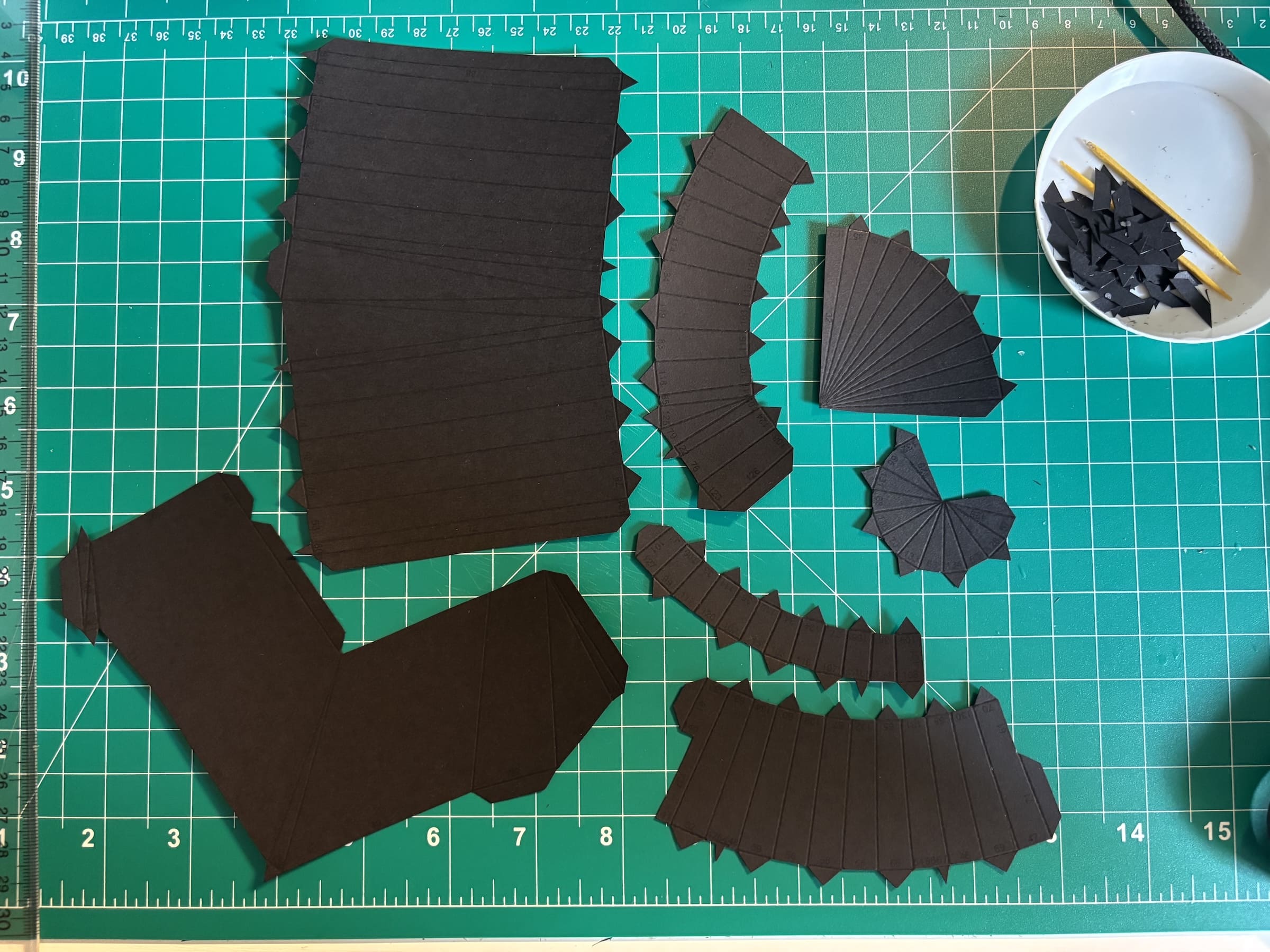
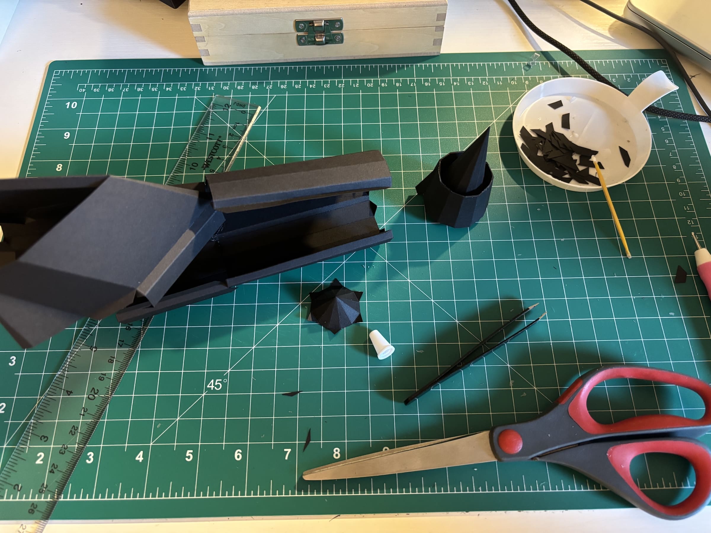
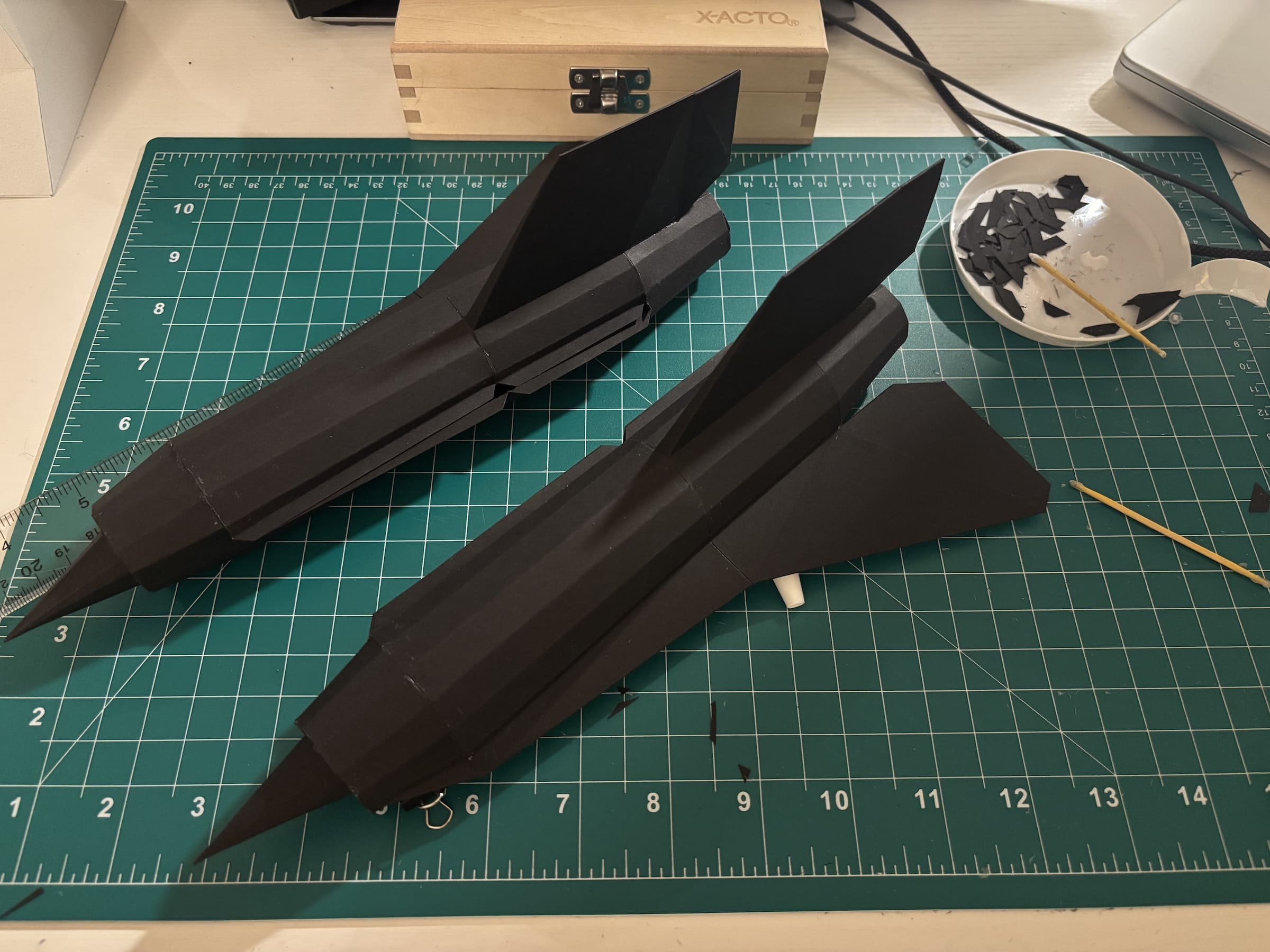
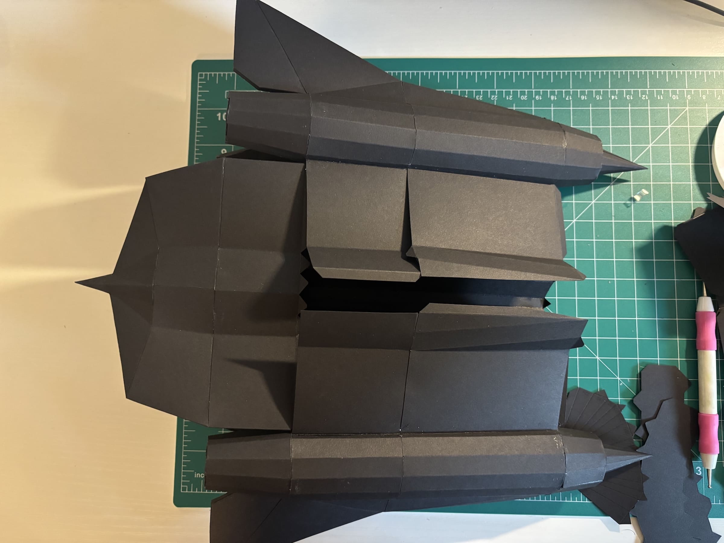
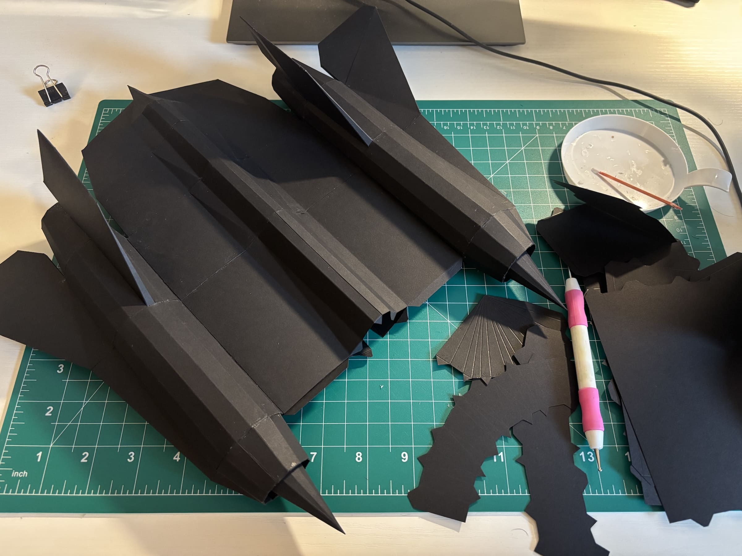
To strike a balance, the approach I took for this model was performing the phases at the granularity of sections (engines, wings, fuselage, etc.) of the model. This approach has the added final step of assembling all the standalone sections together into the final model.
Here's some pictures I took during the assembly process. In total, assembly took 6-8 hours.
Tips#
Use little glue: When gluing parts together, apply as little glue as possible. Using too much glue will result in spillover when the flaps/edges are put together, and this spillover is hard to wipe away from a porous surface like paper. Too much glue can even result in subtle paper warping. In the recommended tools, I suggested a toothpick. I apply a small bead of glue to a flap and use the toothpick to spread it into a thin film. This prevents any spillage and keeps the model clean.
Start in complex areas: As you progress further in gluing parts together, the degrees of freedom of your model will reduce. This is why I recommend starting with more complicated areas of your model where you'll need those degrees of freedom. In this model, this meant starting with precise features, like the engine inlet spikes or the vertical stabilizers.
Finish in hidden areas: This goes hand in hand with the tip above. As you reach to the end of your model, gluing the final parts together can be very hard, which means the final edges may come out a bit sloppy. Why does this happen? Any minor imperfections we made throughout the assembly process result in stresses in our model that will be felt at the end. Gluing the last part may be challenging because it'll feel misaligned, and it has the added challenge of attempting to close a 3D object from the outside. That's why I always recommend choosing an assembly order that results in the last parts being glued in an area that is out of sight. For the SR-71, that happens to be the underside of the fuselage.
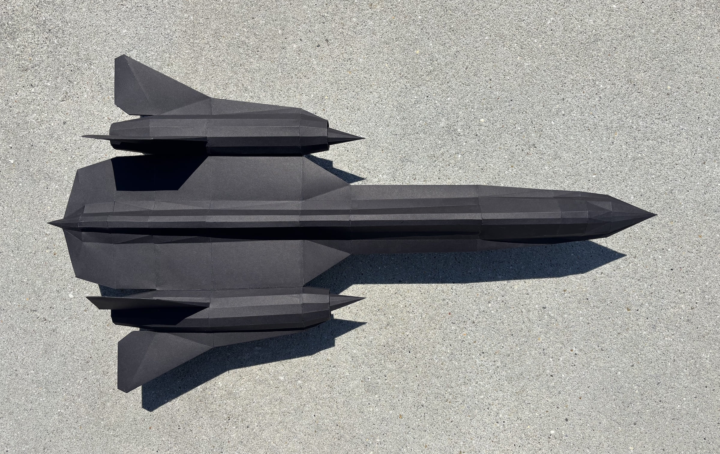
Final Model#
Here's the final model, displayed on a stand (also made from paper):
Iteration#
No matter how much you scrutinize the modeling and layout phases, you will inevitably find areas for improvement as you assemble. In the case of the SR-71, I spotted a few minor asymmetries in part tabs, and more importantly, an opportunity to reduce face count by simplifying the topology of the bottom of the plane and the nose cone.
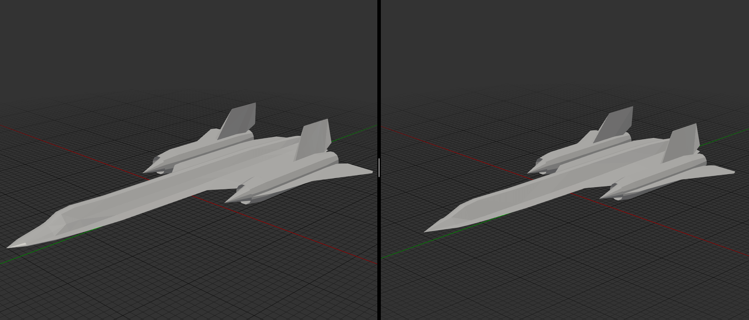
I took my mesh back into Blender, and was able to get the triangle count down to 636, which is almost a full 100 faces fewer than the original mesh.
Below, you can see the old mesh (left) next to the new mesh (right). It's hard to tell the difference, yet the new one has almost 15% fewer faces.
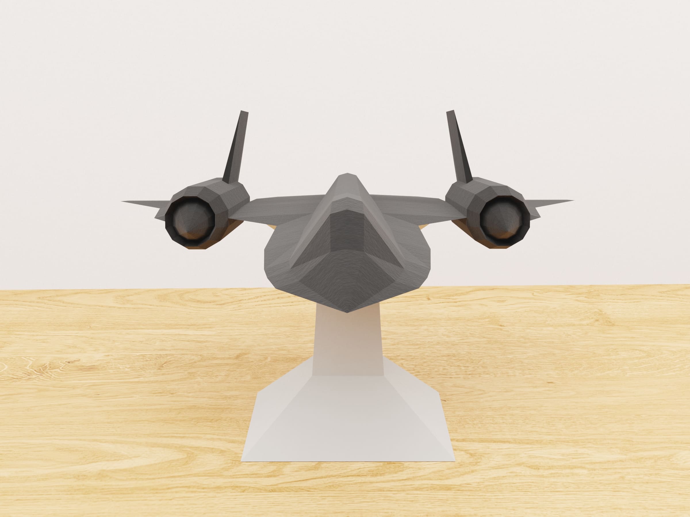
A faster way to iterate is to render the model rather than physically building it. This allows you to quickly identify and fix visual issues without going through the hours of assembly. Here's some renders (in Blender) of the final iteration:

Conclusion#
In total, the full cycle of designing the mesh, creating the parts layout, assembly, and subsequent refinement iterations occurred over the course of a few months. The process is long, but the results are well worth it.
If you're interested in making this model yourself, you can download the PDFs for the first iteration of the model below. I've included a template for the stand as well.
Hope you enjoy!